Jose L. Agraz, PhD
Finger ForceFinger Force : Methodology

Introduction
Prerequisites for the design of the sequential force measuring system were
that it had to be designed to be used in typical situations, be easy to operate, and be
inexpensive. Design considerations were based on the idea that it was to be a "plug
and use" system, since non-engineering personnel would be using it. The system
should be usable in various environments, so it must to be relatively insensitive to
ambient temperature changes. A regular computer keyboard was rejected as the
user interface since keyboard use varies from individual to individual and it would be
difficult to standardize the wrist, hand or finger placement. Therefore, a specialized
keyboard that minimized biomechanical differences was outfitted with robust sensors
Software considerations included the need for visual feedback to the subject,
to insure that persons generated the same amount of force every time that they
struck the key, and isotonic force data had to be recorded and stored. Based on
other exercise studies, 80% of the isometric force value was taken as the target force
value that each subject had to generate for each depression. Hence some form of
visual feedback system of the force generated by the subject was required for the
exercising of the subject. Another software consideration was that each force profile
was to be visualized simultaneously in real-time from the time of onset of key
depression and release. All force data would be saved and a fitted curve to the data
would be plotted. Finally, an electronic record of each subject would be gathered
previous to the data collection process, and would be stored with the force data.
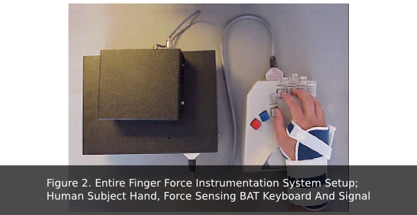
This study measured finger force by using five resistive-based technology
force sensors placed on the surface of individual keys to measure finger force for all
five fingers, individually or in a group, on an ergonomically designed keyboard
(Figure 2). A 16-bit data acquisition (DAQ) PCI (Peripheral Component
Interconnect) card model number MIO-16-4 from National Instruments was used to
capture the data from the five resistive-based force sensors. LabVIEW Software was
written to record pertinent subject data, visual feedback of the force level each
subject was required to maintain, and a best-fit plot of all data points, as well a curve
to best fit the data.

Hardware and Software Design
The need for a "real time" data collection program with a graphical user interface (GUI) front end, demanded an industry-standard data acquisition system. The software that displayed the force profiles was developed using LabVIEW from National Instruments for Windows. The software ran on a generic personal computer (PC), AMD 300MHz, 64Mbytes of RAM with a Windows 98 operating system (OS).
Description of Hardware
Three sets of hardware are used: force sensing keyboard, DAQ card, and signal-conditioning unit. (Figure 3)
The Force Sensing Keyboard
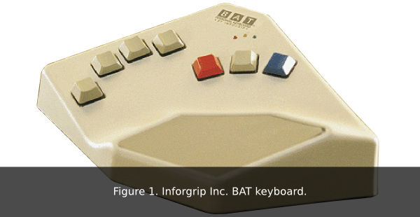
The ergonomically designed seven key keyboard from Biomechanical Advanced Technology (BAT), is part of a design from Infogrip Inc. from Ventura city, California. This keyboard is used to increase typing speed. By using simple sets of key combinations that would represent letters, words, sentences, and even paragraphs. The BAT was chosen for its unique ergonomic design that reduces hand strain and fatigue by controlling the wrist angle. Only the keyboard shell and the key switches were used, the actual typing of words was not needed in this application (Figure 1)

Sensor Evaluation
Prior to choosing the resistive-type sensors from Tekscan (SSB-T), other
sensors that could be placed in the BAT keyboard were evaluated.
The following transducers were considered:
Piezoelectric Film and Coaxial Cable Theoretically, a piezoelectric film
sensor and a piezoelectric coaxial cable could be used, however the coaxial cable
sensor size was too long and the film sensor was too small for use on the BAT
keyboard. Thus the difficulty in positioning these sensors and their absorption of
thermal energy (8v/°K) in the 7-20μm range made these types of sensors too
cumbersome and too sensitive to environmental temperature changes to be
workable. Under ideal conditions, the film sensor is capable of detecting human body
heat radiation up to a distance of 50m (Piezo film sensors technical manual, Aug 98,
Measurement Specialties, Inc., Valley Forge).
Strain Gauge Strain sensors would work as well as the piezoelectric coax
cable in theory. However, they are also very susceptible to environmental
temperature changes as the piezoelectric material above, and posed major
difficulties, and were thus rejected.
Semiconductor Pressure Sensor Pressure sensors were also considered,
but the required retrofitting of a keyboard, using hoses and fluid to measure multiple
pressures, was considered too cumbersome and not practical.
Load Cells Load cells were also considered. However, their high cost
($500/Cell), large size and weight offset their accuracy, leading to their rejection.
Resistive-based Technology (SSB-T) Force Sensor After an extensive
literature review, only one study was found for a device used to measure sequential
finger force generated from the keyboard. This method used SSB-T sensors
(Tekscan in Boston, Massachusetts) placed underneath piano keys. Resistive type
sensors are ideal for this force-voltage type of instrumentation. Because of its
linearity, flexibility, size, cost and minimum conditioning-hardware needed, the SSB-
T sensor was considered the most appropriate for this application.
SSB-T Sensor Output Characteristics:
- Repeatability: within 5%
- Linearity: up to 80%
- Hysteresis: 50% loaded is less than 4.5% of full scale
- Drift: constant load less than 3%/log time
- Temperature: 0.2% per °C.
The SSB-T sensor is an ultra-thin (0-0.03"), flexible printed circuit. It is 0.5" wide and 6.3" in long (Figure 4). The force sensing area is a 0.25" diameter circle at the end of the sensor. The sensor’s area is constructed of two layers of polyester film substrate coated with a layer of silver, followed by a layer of pressure-sensitive ink. An adhesive laminates the two layers of substrate together to form the sensing area. The active sensing area is delineate by the silver circle on top of the pressure- sensitive ink. Silver extends from the sensing area to the connectors at the other end of the sensor, forming the conductive leads. SSB-T sensors are terminated with a 3-pin Berg Clincher connector, which allows them to be incorporated into a circuit.
Force applied to the active sensing area causes in a change in the resistance of the sensing element; inverse proportional to the force applied. When the sensor is unloaded, its resistance is very high, and, when a force is applied, the resistance decreases.
Sensor Keyboard Installation
The SSB-T sensor was installed by sandwiching top and bottom sensors between a keycap and a force puck. The force puck was added to concentrate the force applied with the fingertip within the sensing area of the SSB-T. Prior to the installation of the sensor, the surface of the keycap was initially leveled by placing resin in its well, so as to have a flat, smooth surface. Next, a 1" x 1/8" slit was carved on the keyboard shell to connect the sensor flat wire to the electronic circuit inside the keyboard unit. Since the keyboard was retrofitted with the SSB-T sensors, it was necessary to isolate the key switch. Therefore, the copper clad traces connected to the switches were cut out, and wires were soldered from the switches' terminals to the 25-female connector installed on the front of the keyboard shell
Data acquisition card
The DAQ PI-MIO E card is a jumperless and switchless data acquisition
board that uses the DAQ-STC as the system timing control. DAQ-STC is the
backbone of the sensor system and the timing control application specific integrated
circuit (ASIC). The DAQ-STC contains one 24-bit counter and three 16-bit counters.
The counters are divided into three groups:
- Analog Input--two 24-bit, two 16-bit counters
- Analog output--three 24-bit, one 16-bit counters
- General purpose counter/timer functions–two 24-bit counters
The board is set up in the following data collection mode: non-referenced single-ended (NRSE). A channel configured in NRSE mode uses one analog channel input line, which connects to the positive input of the Programmable Gain Instrumentation Amplifier (PGIA). The negative input of the PGIA connects to the analog input sense (AISENSE) connection
Signal Conditioner and Power Supply Boxes
Digital Conditioning Circuit. This circuit conditions the "on/off" switch
position signal produced by the cherry switches in the keyboard, and
supplies the signal to the DAQ card in the PC. The cherry switches in the keyboard
are set to “high” using a pull-up resistor R 1 , then a NOT gate U 1 (7404), which drives
a Light Emitting Diode CR 1 (LED) and feeds the signal to the DAQ card in the PC.
The LED functions as part of a troubleshooting tool to detect any broken wires
between the keyboard and the signal-conditioning enclosure. The LED
turns off if the switch is pressed. If the LED stays on when the key is being pressed,
then there must be a wiring problem in the system.
Analog Conditioning Circuit. This circuits condition the analog signals from
the force sensors.
5-Volts Reference:This circuit is the first stage of the force-to-voltage converter
A steady voltage reference chip (Maxium MAX6250) is used as the
excitation for SSB-T sensors. The MAX6250 is a low-noise, precision voltage
reference with extremely low 1ppm/oC-temperature coefficient and excellent ±0.02%
initial accuracy.
Preamplifier: The preamplifier circuit, along with the SSB-T sensor, was designed
to convert force applied to the keys into an electrical signal. This circuit uses a low
noise operational amplifier (Burr-Brown OP27) in a single-ended arrangement to
produce an analog output based on the SSB-T sensor resistance and a fixed
reference resistance R 1 . Also, the circuit includes a 10-turn potentiometer (R 2 ) as a
signal-gain control that provides a better resolution during the gain-calibration
procedures.
Output Filter: The output filter circuit was designed to block high frequency noise
picked up from the surroundings and produced by the circuit. The filter is composed
of components R4 and C1 with a cutoff frequency of 63MHz. Also, the circuit
includes an offset control composed of resistors R 6 and R 7 , and a 10-turn
potentiometer R 5 that provides a better resolution during the DC offset calibration
procedures.
Power Supply. The power supply enclosure contains a ±12V supply that
powers the analog components and a +5V supply that powers the transistor-
transistor logic (TTL) components.
Key Force Calibrator
In order to test the linearity of each SSB-T sensor, a calibrator was
constructed to provide a wide range of forces that could be compared to the voltage
output of the circuit. This device consisted of a rectangular platform
which had two levels attached to its surface. Attached to the platform was a 4-inch
brass bolt that was held in placed over each key by two micromanipulators. Weights
were placed on top of the platform and corresponding voltages recorded.
The calibrator was positioned on top of the keycap puck. To
insure that a straight-down force was exerted on the keycaps by the calibrator, both
levels on top of the calibrator had to be level. Thus, a real force contrary to a
complex force value would be applied to the SSB-T sensor. Lead weights up to the
reported sensitivity of SSB-T sensors were placed incrementally according to their
weight onto the rectangular platform and the corresponding voltages were recorded.
Description of Software
The software collects information about each human subject. This database
consists of; (1) calibration information from isometric exercises, (2) displays of the
isometric force levels, and (3) force-data from the user, collected when typing on the
BAT keyboard. In addition, the software generates plots of all force-data separately
for each key.
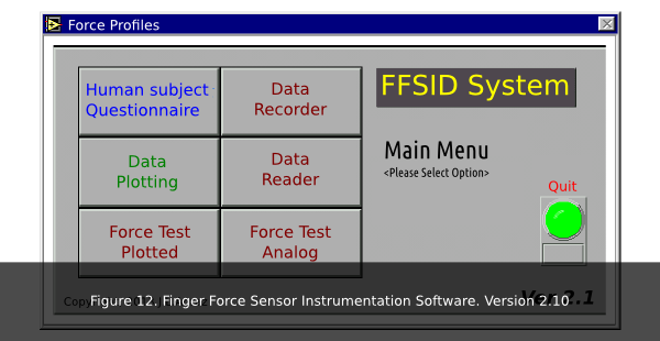
The software component of this system was programmed using a graphical
user interface (GUI) programming language called LabVIEW. The short learning
curve and the capability of providing an exceptional user-friendly interface made this
program language the best choice (Figure 3.12). The programming was done by the
use of LabVIEW Sub Virtual Instruments (VI), or procedures, as on text
based programming languages as C, Assembly or Fortran.
The software goes into to a loop waiting for the user to click on any of the
buttons on the screen. Once the subject presses a
button, the program executes the appropriate VIs.
In addition, the data-collection program uses an “ini” file that controls and
stores the parameters within the program. Data stored includes; sampling frequency,
calibration coefficients, isometric parameters, data file path, and initial sound and
channel settings. The purpose of this feature is to decrease the amount of time
required for the development of the system. When all the variables are stored in a
single easy-to-access file, changes can easily be made to the program without
recompilation. The program will search for the file “force.ini” containing the
information previously described. This “force.ini” file is formatted according to
Windows “ini” file standard format such as labels (placed within square brackets)
and items that follow immediately.

Human Subject Testing
The objective of this study deals with the development of systems that can easily and accurately measure the generation of sequential finger-force. Limited experimentation was conducted using students at San Diego State University (SDSU) to evaluate the applicability of the system. Human volunteers used the sequential finger force system. Initially, subjects were required to depress the key in time to a metronome set at 1 stroke per second. This test evaluated the reliability and durability of the device. Subjects were seated comfortably and the sequential finger force-measuring device was placed so that their right elbow would form a right angle with the humorous bone. A second set of experiments consisted of the subjects depressing the index key in a typing motion until the onset of fatigue.

 Introduction
 Anatomy
 Methods
 Results
Feb 14th, 2015 at 5:09 pm